Computer Hardware Assembly Guide
-
PICTURE INTENSIVE WARNING
Computer Hardware Assembly Guide
Before assembling your system, you need to have parts to build. You can take a look at the possible configurations over at the DIY PC CONFIG GUIDE
General Components of a System:
Central Processing Unit + Motherboard/Mainboard(Short form "mobo")
Random Access Memory (RAMs)
Graphics card/Graphics processing Unit(GPU), if your motherboard does not comes with onboard graphics
PowerSupplyUnit(PSU)
Hardisk
DvD Drive
Casing/Chassis- it is important to buy a casing that will fit your motherboard's formfactor(the size) and graphics card(some high end graphics card are very long and may not fit in small casings)
Other possible components:
Soundcard
TV Tuner
Wireless Adaptor
Tools needed:
1.philip head screw driver, best to have a magnetic tip to retrieve screws stuck in hard to reach area in the
casing.
2.Torchlight(optional), most of the time not needed
Step One: Prepare the Casing for installation
===================================================
Installing the Power Supply if your casing does not come with it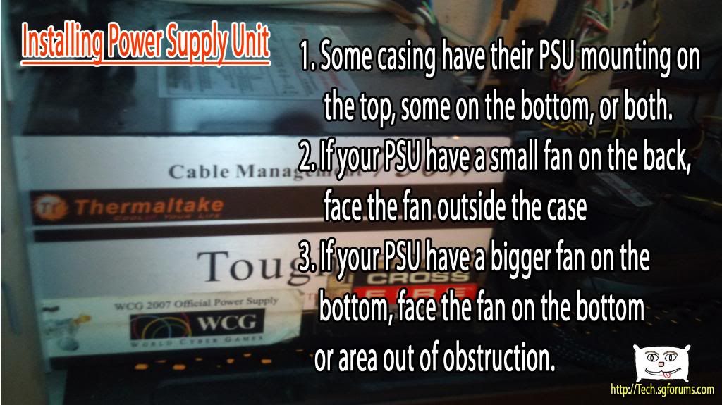
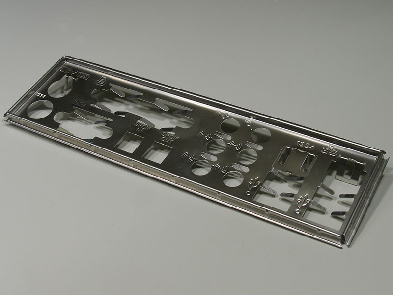
Take out the I/O shield from your motherboard's box,:
*Picture taken from http://www.techpowerup.com/articles/144/images/6ioshield.JPGLine it up with the back of your motherboard to determine how it is oriented. Usually the input for keyboard and mouse are on top.
YOUR I/O shield may be used for other models of motherboard with similar design, thus, you will find extra holes on your I/O shield, usually this is covered. However those covered holes can be broken off easily to fit your motherboard's I/O.
You may also be bigger 'metal fins' that is covering certain ports like-PS/2 keyboard or the lan port- just push them all the way back so that it does not block the ports after installation backpanel or I/O of motherboard: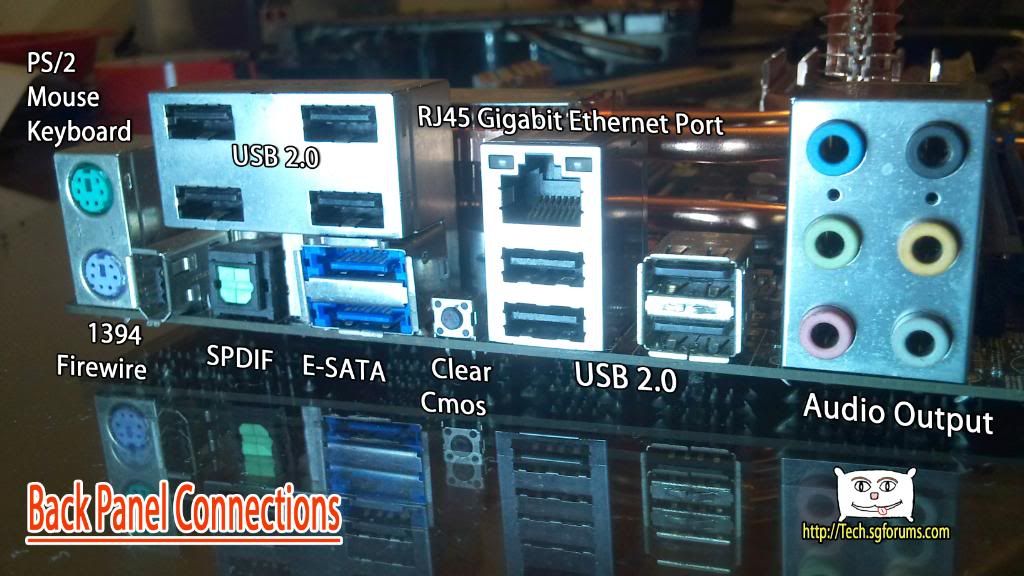
When you look at your case, it may have already come with a I/O shield, if it fits then you can use it(most of the
time it will not fit), or if not you can use the one that comes with your motherboard
Install it at the upper top at the back of your case, after installation, it will look like this: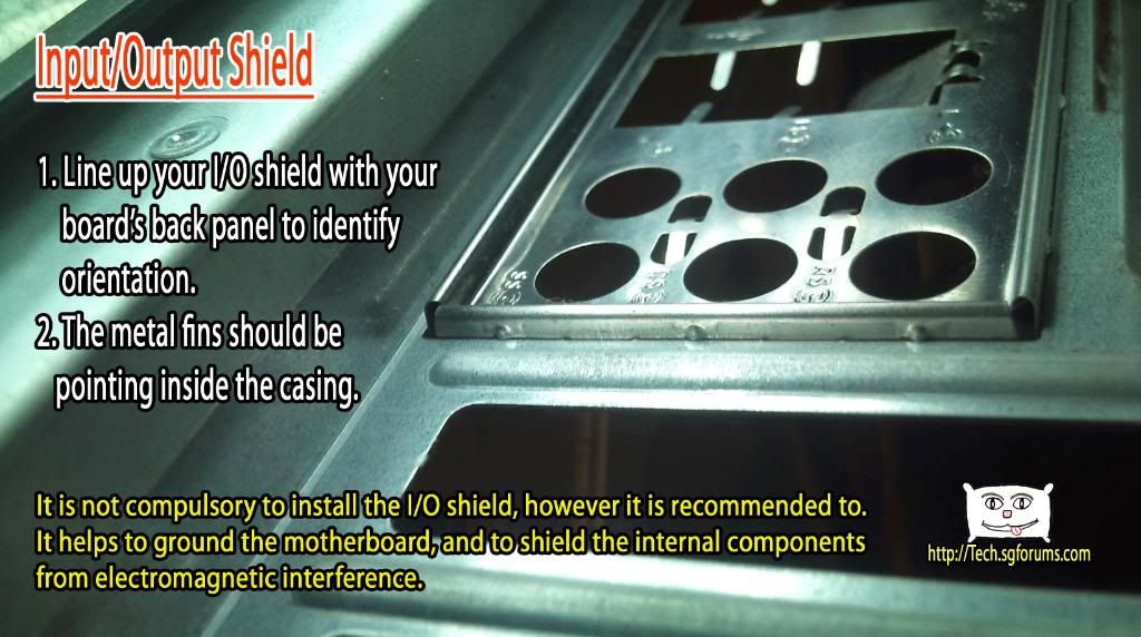
-----------------------------------------------------------------------------------
Also inside the Case you will find a series of screws.
See which screws are for which components here
Different screws are for different components, but if the screw fits securely without the need of excessive force, it is fine
Some casings are tooless, meaning the case allows you to install components like DVD drives and hardisks without the need of screws.
There are also casings which comes with fitting to secure your graphics card without screws.
It is fine if your graphics card is not very heavy, but if you are running a high end graphics card with large heatsink, it is recommended to use screws instead to secure the card
-------------------------------------------------------------------------------
Now for the more important type of screw, called spacers/standoff: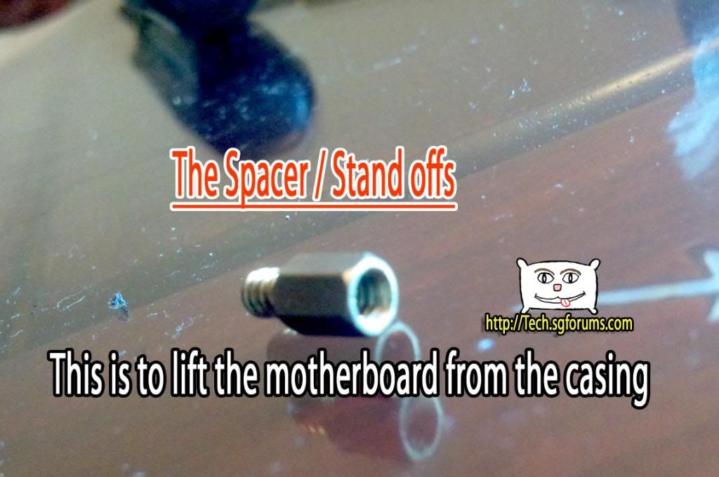
This is to be screwed onto the PREDRILLED holes on your casing.
Location to install these standoffs are depended on the form factor of your motherboard.
The easiest way is to look at the motherboard, and look at the casing to determine which are the mounting holes.
Mount the stand offs
------------------------------------------------------------------------------------
Leave your case aside for the moment -
Step two: Prepare the motherboard for installation
===================================================
Mounting the CPU, the most dangerous part of the assembly
Most frequently asked: How orientation should i fit the CPU into the socket?
Basically this is what you need to know about the CPU, in terms of assembly: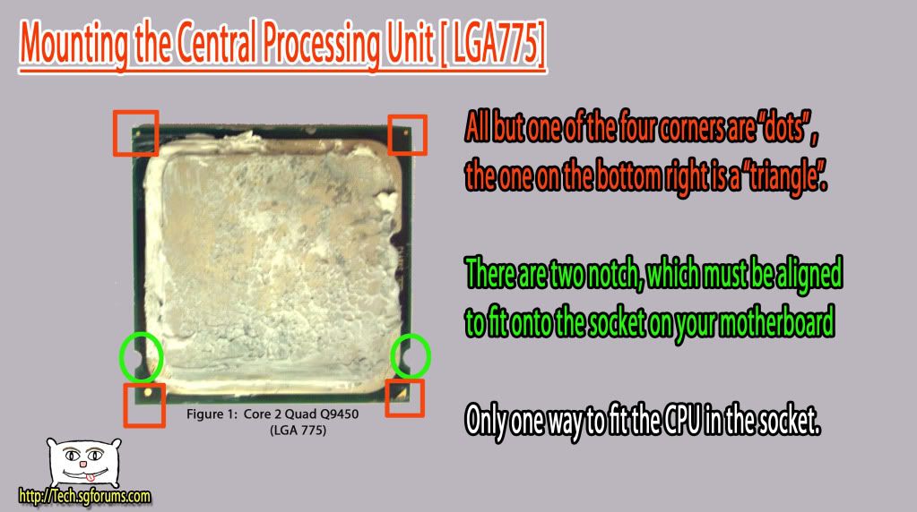
This is what is on the socket: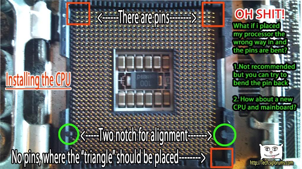
Line up the triangle and notch so that they fit like this: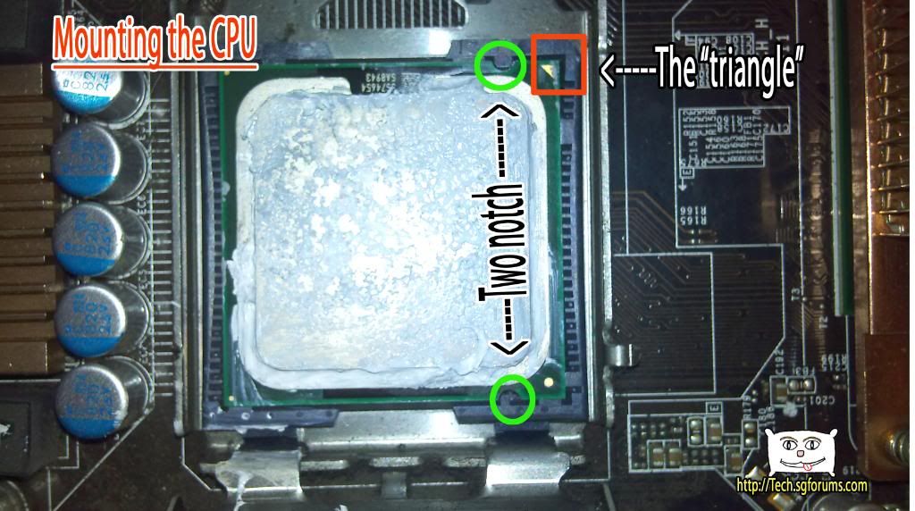
After that, close the cover and secure the cover using the lever like so: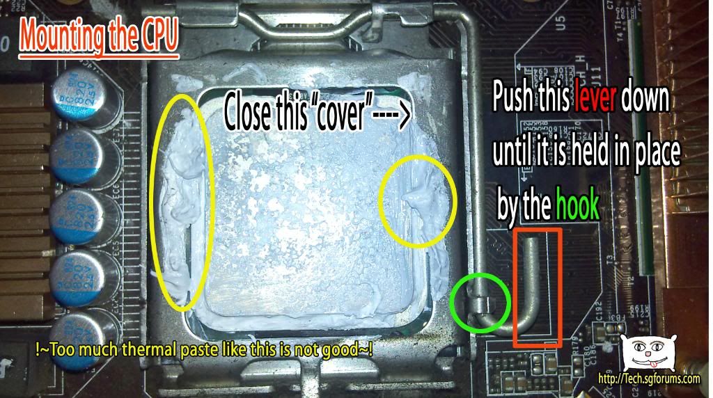
---------------------------------------------------------------------------------------
After mounting the CPU, it is time to mount the CPU cooler
Do not worry, the intel stock cooler comes with thermalpaste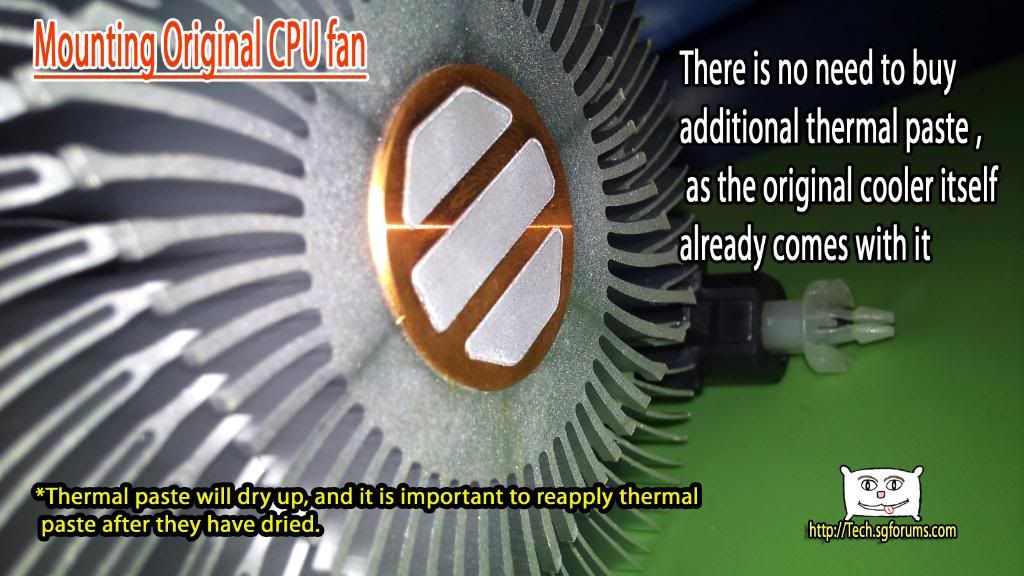
MAKE SURE THAT THE FOUR 'LEGS' of the cooler looks like this: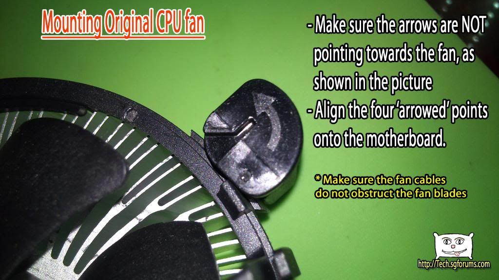
Place the cooler ontop of the processor, and you will realise that the legs of the cooler is positioned above the mounting holes.
Firmly press the four legs down like shown in the following picture, make sure the four legs are positioned like what is shown on the previous picture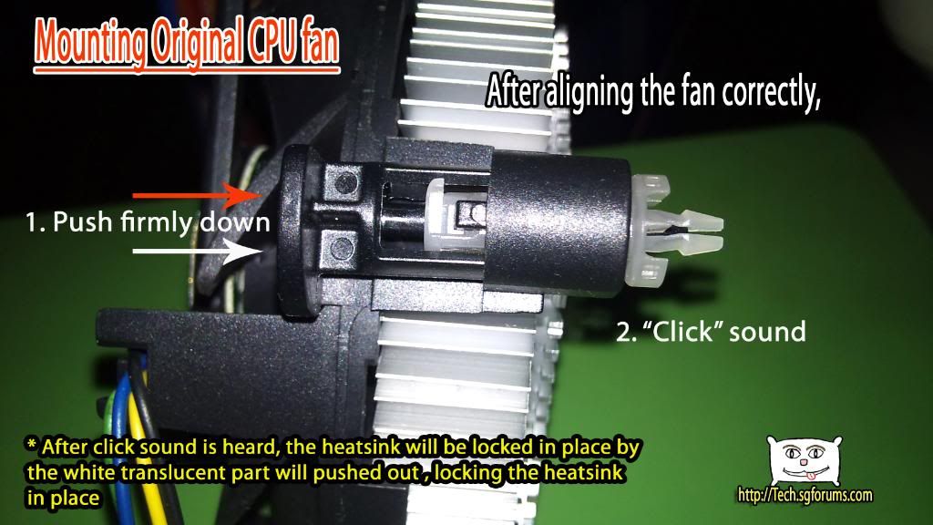
In case you have problems fitting all the four legs perfectly and would like to take out the cooler, follow the following picture: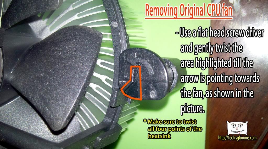
-
Step two: Prepare the motherboard for installation(continued)
================================================
After mounting the fan, be sure to plug in the power, the power connector for the cpu fan looks like this: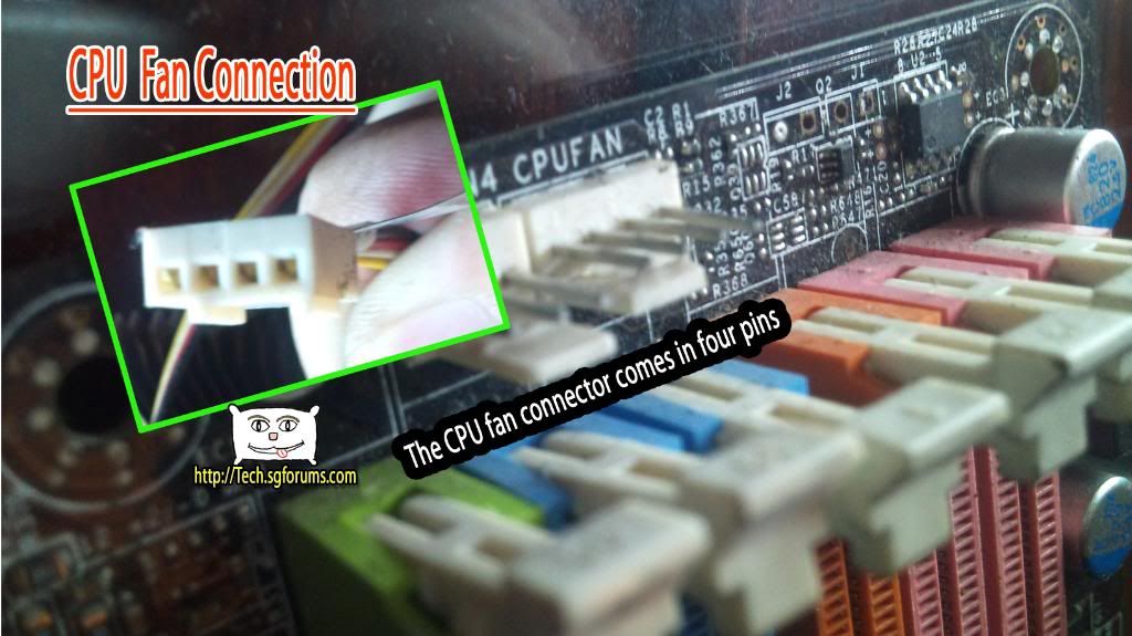
Now it is time to install RAM
Some infos about rams and the slot: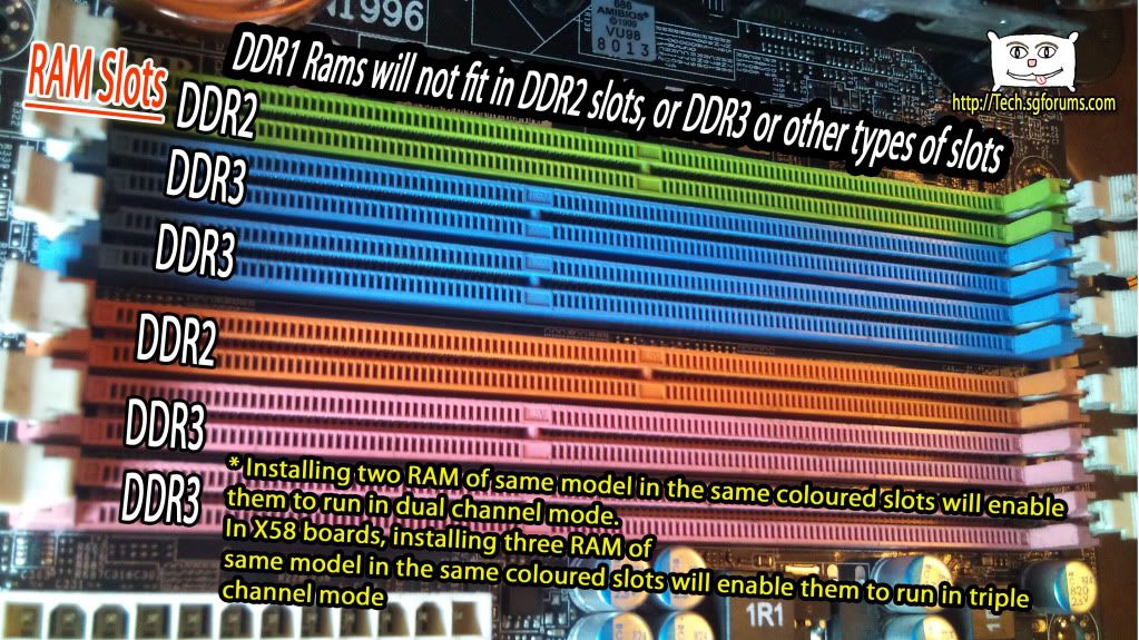
So you bought your ram, install the ram like in the following picture. Dont worry if your ram look different, they way of installing is the same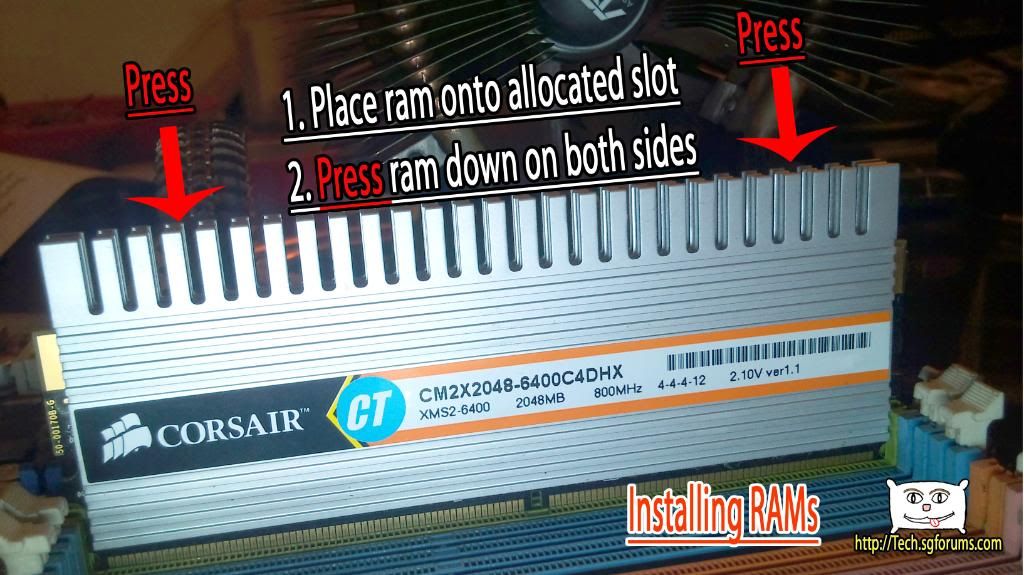
---------------------------------------------------------------------------------------
After mounting the cpu, heatsink and ram, it is time to install the motherboard back into the case. Make sure you have your stand off screwed onto the case.
Your motherboard will look something like this(On the pictures are some name of the expansion slots):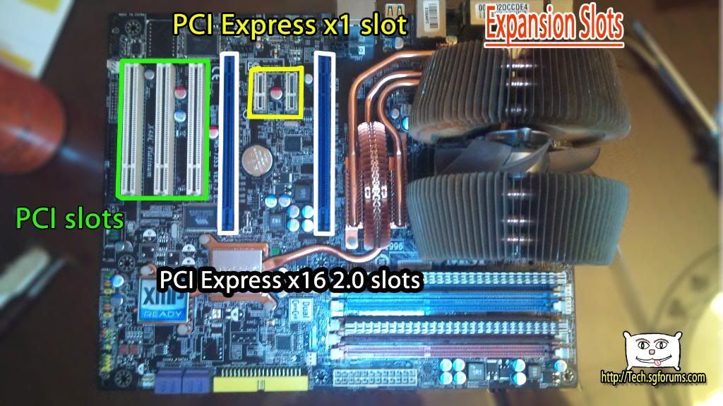
Do not tighten all the screws! Because you need to check that the I/O (back panel) of the motherboard is line up nicely with the I/O shield. If you tighten all the screws and the board does not line up, you will need one extra step
Now that the motherboard is fitted on to the case, lets move on
---------------------------------------------------------------------------------------
If your motherboard comes with onboard graphics, and you dont wish to install an graphics card, you can skip this step
The thing at the bottom of your graphics card that allows you to slot it in your motherboard is called PCI Express x16 slot. The interface design of older graphics card is called AGP slot, and there are also other types of graphics card with different interface
This is how it looks like: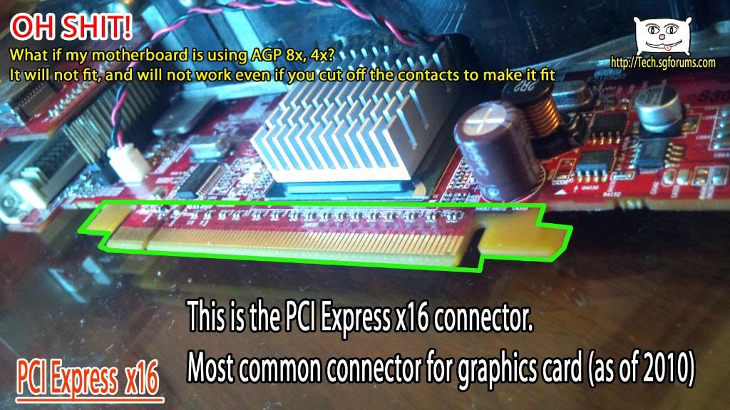
This is how you put it in: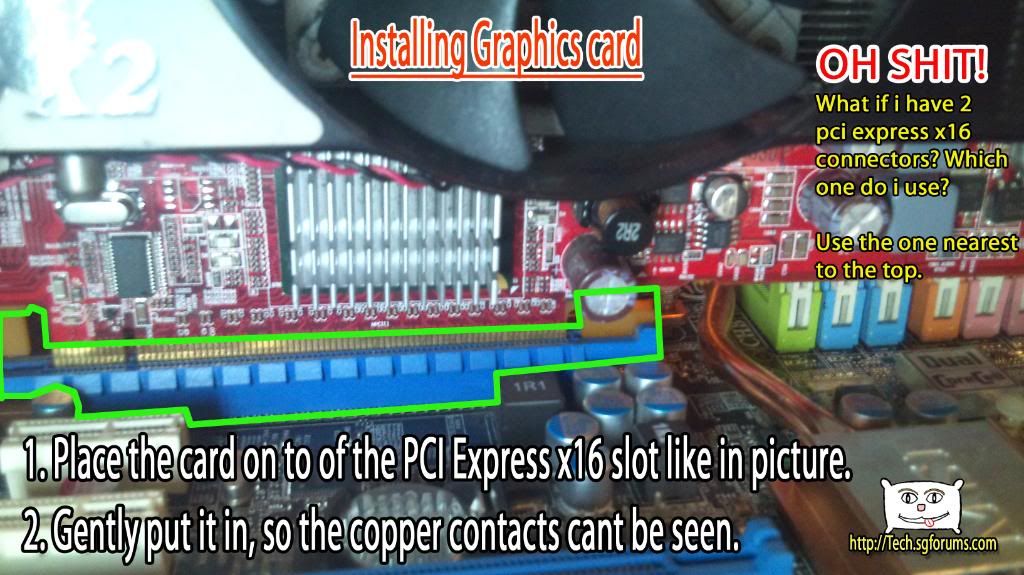
NOTE THAT in the illustration above i didnt mount the motherboard into the casing, because it will be hard to take picture. Please mount the mainboard onto the casing before installing the graphics card, it is safer and easier -
Step three: Mounting DVD Drive/Hardisks/Diskette on your casing
============================================================
Unfortunely i do not have pictures for this section, but fortunately this part is the easiest of all
Check out these two videos, it is very simple, just slide it into the bay and tighten it.
How to install a Hardisk Drive
Just so happens if you use a diskette drive, here is some information: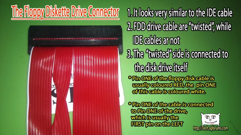
-
Step Four: Connecting the power Cables
================================
Most important part is to bring power to the components
Lets start with the motherboard. Your motherboard will need a 24pin and a 4pin/8pin/Dual 8pin Power.
This is how the twenty four pin connector on your motherboard look like: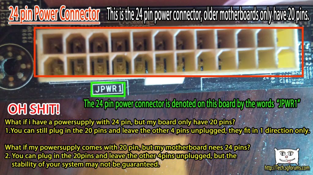
THIS MUST BE FITTED WITH THE PSU's 24pin, which looks like this: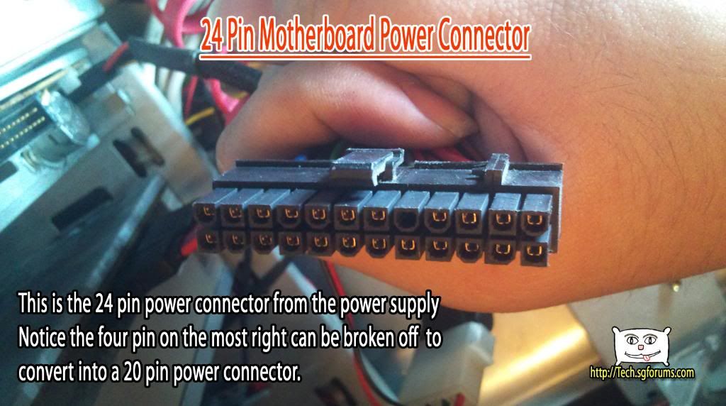
There is only one direction in which you can plug it in.
This is how the 8pin Power looks like: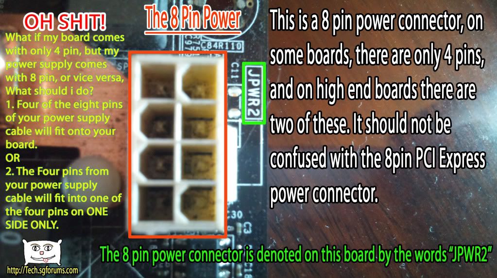
THIS MUST BE FITTED WITH THE PSU'S 8pin, which looks like this: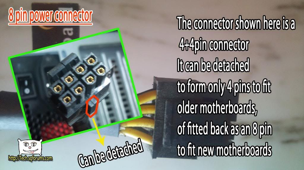
That is all for connecting the motherboard
----------------------------------------------------------------------------------------------
Now it is time to connect the power and data cables to the dvd drive and hardisk driveYou will need SATA Power and SATA Data Cable
This picture show where to connect your drive to on the motherboard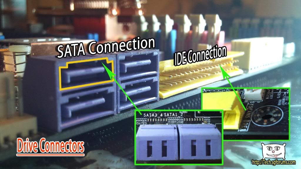
This shows the interface behind the dvd drive, which is the same as the harddisk drive
If you are interested to know how it looks like when connected, here: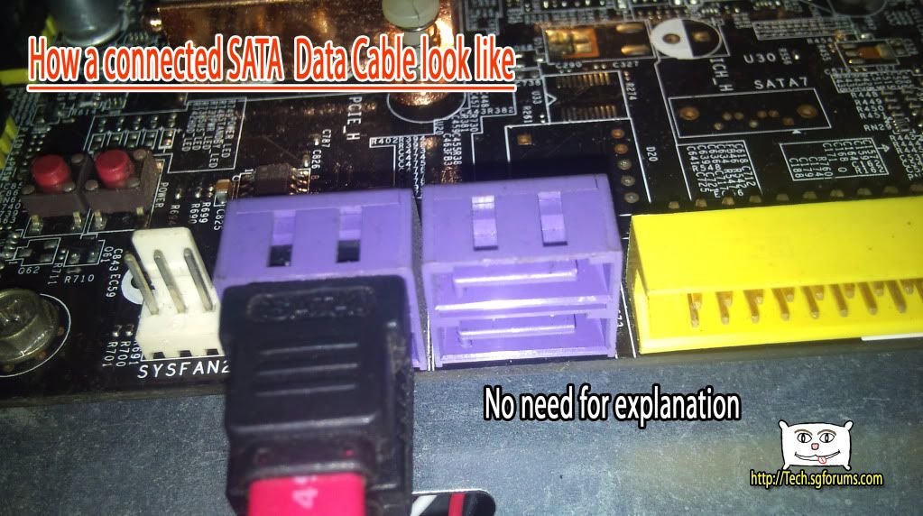
If your powersupply doesnt comes with sata power, you can buy a Sata power to molex adaptor. -
Step Five: Connecting the motherboard to the casing, and USB Headers
============================================================
Computer Casing comes with Power switch, Reset switch, USB ports, Headphone/Mic Jacks, Power LED and Hardisk activity LED
This picture shows how to connect the Powerswitch,Reset switch, PowerLED, Hardisk activity light and the buzzer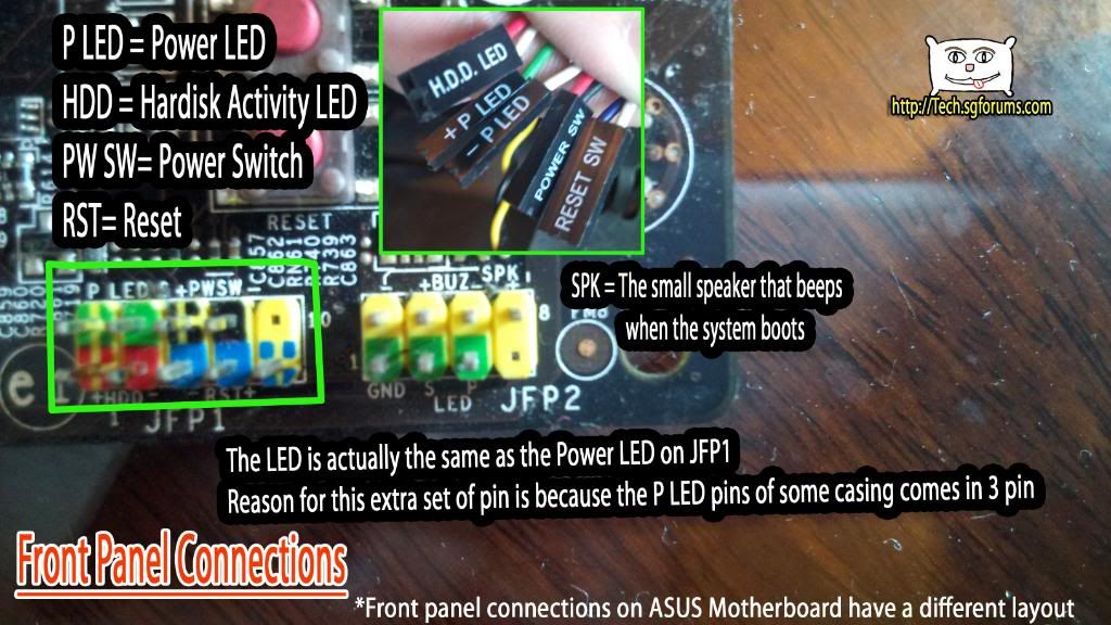
Addon: The positive of the connection is 99% of the time on the left, at least for motherboards nowadays. Im not sure if older motherboards have their arrangement the other way round.
This picture shows how to connect the USB headers:
This picture shows the connection for Front Panel Audio.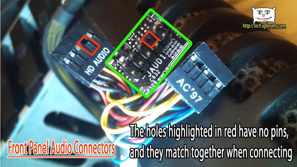
Note that you see HD Audio and AC'97 audio connectors.
Motherboard nowadays are using HD audio(as of 2010), however some casing's front panel audio is still using AC'97
What can you do:
1. If you insist that you want to you the front panel audio jack, you can confugure the setting in the bios to change your system's audio to AC'97. However it will not sound good, as HD audio is of better quality than AC'97
2. Before buying a casing, make sure it comes with HD audio front panel connector.
3. Make one yourself -
Nice guide!
